A Solutions Based Approach From a Thermal Remediation Perspective
By: CascadeThe word “solution” is defined as “a particular instance or method of solving” by dictionary.com. We all know that there are often many solutions to one problem, depending on the desired outcome and/or set of circumstances surrounding that problem. That is exactly how we approach remediation projects at Cascade. Our clients have access to a team that can expertly implement a range of remediation technologies, individually or in combination with each other. Using real time data, we are able to adjust the conceptual site model and remedial plan as conditions change to achieve the ultimate project goal.
As described in last week's blog post, site conditions often govern the choice of technology, and one needs a strong Conceptual Site Model (CSM) before the proper choice can be made. A strong CSM helps define all the different geological factors you are dealing with so that you can choose the right technologies to remedy those different areas. This is no different when considering thermal remediation technologies. As shown in Figure 1 below, the thermal sweet-spot is the more heavily contaminated source zones, which can all be defined in the beginning with your CSM.
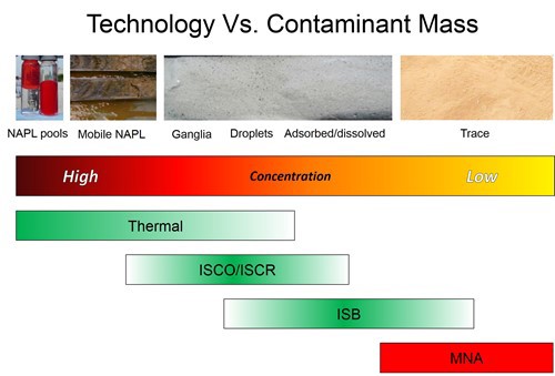
Figure 1. Scale of contamination with technology sweet-spots indicated.
Thermal is a big hammer – one that can be used to treat really nasty sites – when used properly. Understanding how each of the three thermal technologies works is critical for designing the optimal thermal design to address your site’s soil, permeability, contaminants, location, and cleanup goals.
NO OTHER THERMAL REMEDIATION COMPANY OFFERS THIS FULL RANGE OF OPTIONS, INCLUDING:
- Thermal Conduction Heating (TCH),
- Electrical Resistance Heating (ERH),
- Steam Enhanced Extraction (SEE), and
- Combinations of the above.
These technologies allow us to evolve and adapt to the dynamic field of remediation – providing state of the art solutions for very challenging site conditions, such as:
- Layered sites with low and high permeability and groundwater flow (using SEE to heat the permeable zones and ERH or TCH to heat the tight zones)
- Deep sites (using TCH and SEE to overcome high drilling and electrode costs)
- Sites with extreme chemical mass (using robust thermal oxidizers and corrosion-resistant well materials)
- Bedrock sites (using TCH to heat the matrix and SEE to heat fractures)
Figure 2 (below) illustrates the fundamentals of the three technologies.
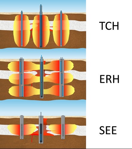
Figure 2. The three thermal technologies.
Evolving and adapting doesn’t stop at the solution; it relies on the frequent and continuous collection of data throughout the project. Clients can follow the progress on their sites in near real-time through our industry-leading data management and visualization software.
Armed with the data from the CSM and our extensive experience of all three thermal methods, we can target specific zones with individual remediation technologies to achieve better overall results:
- We can treat tight zones effectively, using ERH and TCH
- We treat permeable zones using SEE
- Layered sites are optimized by combining two methods and reducing overall cost.
PREPARING FOR THE FUTURE OF THERMAL REMEDIATION
Our environment is constantly producing new demands and so solutions are never one and done. It is essential for today’s environmental professionals to be continually preparing for the future by developing innovative solutions that answer some of the toughest challenges, such as:
- Improved characterization methods which will allow us to refine treatment volumes and minimize cost and resource usage
- Smarter heating techniques which reduce the power and fuel use
- Combined remedy solutions where less energy-intensive methods are paired with thermal
- Lower temperature biological treatment – powered by renewable energy sources
- Improved sampling and progress monitoring to better determine when to stop
The key is to optimize the thermal and complementary technologies to deliver the most cost-effective remediation solutions– both the source areas and the plumes, as illustrated by the four typical zones shown in Figure 3 (below). No one technology fits in all four zones – our challenge is to find the best combinations to treat your particular site.
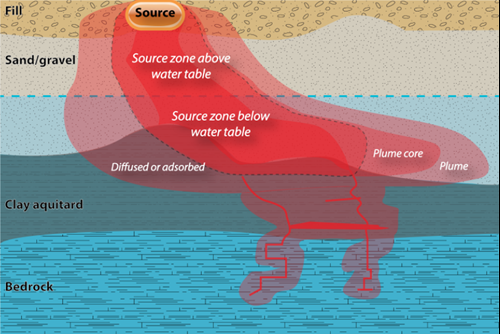
Figure 3. Typical conceptual site model and zones for technology selection. The best solutions involve the selection of technologies which are effective in each zone.
Join our newsletter

A bimonthly email with the latest expert insights in drilling and remediation