How to Optimize Injection Performance and Distribution Through Manifolding Multiple Injection Locations
By: Eliot CooperAs our industry becomes more sensitive to the importance of distribution of in situ amendments to achieve contact with contaminants like TCE, Benzene and Hex Chrome, injection flow rates and related pressures are being reduced to avoid fracturing target intervals in transmissive soils. At the same time, higher injection volumes are being required to rely less on advective distribution especially for sites with low seepage velocities.
Because lower injection rates and higher volumes can equate to higher remediation costs, manifolding multiple injection points, whether direct push or injection wells, is now a cost-effective solution to optimize overall injection performance. In this article, we will discuss design considerations for manifolding as well as additional steps needed to provide input to fill some data gaps.
EVALUATING MAXIMUM INJECTION FLOW RATES
When deciding how best to manifold injection locations, there are design considerations that must be evaluated to optimize costs; however, the first important design consideration is based on a field evaluation of what maximum injection flow rates can be achieved within each target interval or intervals without fracturing the saturated soils. While the term “pilot testing” has been used extensively in the past, new terminology—“Design Optimization Testing (DOT)”—is now applicable to the first critical step in optimization while still maintaining the contact required for contaminant destruction.
UTILIZING DESIGN OPTIMIZATION TESTING
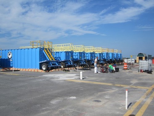
Ideally, the DOT injection location and target interval is first defined through advancement of high resolution site characterization (HRSC) tools, which will provide a screening of contamination mass versus soil type as well as hydraulic conductivity. Cascade performs the DOT as an add-on service to any HRSC engagement, e.g. Membrane Interface Hydraulic Profiling Tool (MIHPT) or determining mass flux with our WaterlooAPS. The Next Generation Injection Manifold System, shown below in a demonstration at Battelle 2018, can be mobilized to perform DOTs on site.
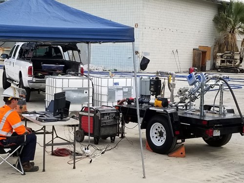
Figure 1 – DOT Next Generation Automated Injection Manifold
A DOT, typically with water or the selected liquid reagent, and sometimes a wide range of injection tooling or well screens, is injected while measuring flow versus pressure (and mounding at neighboring wells if it’s a concern) at each target interval. Flow rates are increased until a fracture is identified, which is typically estimated at 0.5 to 1 PSI per foot of overburden above the injection zone. For example, for a well screened from 20 to 30 feet, the maximum injection pressure could be estimated at 10 to 20 PSI. Note that this is down hole pressure and is often difficult to measure, so in many cases down hole pressure is estimated based on pressure losses after the pressure gauge at the injection pump. For DPT injection, where compaction of the side walls of the borehole occurs, injection pressures can be higher without fracturing the formation and, based on experience, can add another 50 to 100 PSI without fracturing the target interval.
Hydraulic fracturing involves injection of fluid into the subsurface at a pressure that must initially exceed the combined lithostatic pressure, hydrostatic pressure, cohesive strength of the formation, and other sources of resistance such as pressure loss through the injection tooling. The lithostatic and hydrostatic pressures are essentially equivalent to the weight of the soil and water columns, respectively, above the depth of injection. The cohesive strength is a measure of how well the soil particles are adhered to one another. Clays generally have significantly greater cohesive strength than sands. Other pressure losses, such as friction from the sidewalls of the injection rods and injection hoses, and compaction of the borehole through DPT displacement of soils, will create additional resistance that must be overcome. Once this pressure has been overcome and a fracture has been created, the pressure required to continue the injection will be significantly lower (see maintenance pressure, Figure 2).
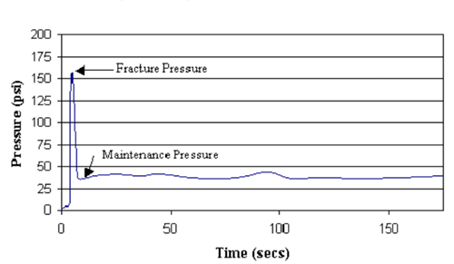
Figure 2: Fracture and Maintenance Pressures
DOTs are typically performed manually by injection operators increasing flow rates with a ball valve, and at the same time recording injection pressures. A fracture is identified by a rapid decrease in pressure and an increase in flow rate. This approach represents current best practice, but Cascade recommends automated over manual systems (see Figure 1 above) with data logging to be able to determine precisely at what flow rate and pressure the fracture occurs or degree of mounding even if fracture pressures are not exceeded. See Figure 3 below for an example of a DOT deliverable.
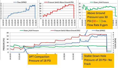
Figure 3 - DOT Deliverable
IDENTIFYING KEY PERFORMANCE AND DESIGN PARAMETERS
Once the DOT is completed, maximum flow rates without fracturing the target interval(s) or acceptable mounding are identified and then can be used to optimize injecting at this rate at multiple locations. It is at this time that one must take into consideration the following key performance and design parameters, including (but not limited to):
- Injection well v. direct push injection
- Drilling and well abandonment time
- Type of drill rig to be used
- Whether straddle packers will be used to isolate intervals
- Gallons of amendment per interval
- The injection time within interval targeted by the injection tool or well screen
- Soil type (whether course or fine grained)
- Whether amendments are liquid and/or solids
- Amendment mixing time and logistics
- Anaerobic water preparation time and logistics
- Groundwater extraction water rates and logistics
- PPE requirements
- In-line dosing of multiple amendments
- Pump pressure versus flow capacity
- Distance between injection locations and whether to inject at adjacent injection locations
- Weather conditions
- Unique site logistics
- Groundwater mounding
- For DPT injection, whether injection tools will remain in the target interval overnight
- The costs of additional DPT injection tooling
The complexity of planning around all of those design considerations necessitates experienced professionals working on your project to ensure opportunities for optimization are not missed. Cascade experts developed a manifold design tool to optimize overall total injection rates and manifolded locations, ensuring that every opportunity is utilized.
On your next injection project, be certain you’ve chosen a contractor that understands the design considerations for manifolding, how to fill data gaps, and is sensitive to remediation costs without compromising results.
If you’d like to learn more, watch our on-demand webinar, “Design Considerations for DPT and Well Injection Manifolding to Optimize Performance and Lower Costs.” Where technical experts will show you how to work through design considerations so you can spec out achievable performance in RFPs, or benchmark whether an injection contractor has optimized your project to the greatest extent practical.
If you are interested in engaging Cascade experts on your next injection project, request a quote now.
Join our newsletter

A bimonthly email with the latest expert insights in drilling and remediation